

Intro
I wanted to use my gate drive system from Hörmann (Hoermann) with an ESP8266. There is an existing Gateway/LAN System from Hörmann the problem with this system I have is:
- It seems to be dependent on the Hörmann Cloud, you have to register at hoermann.de to get the App working.
- There is no Native App for Android, the App relies on Adobe AIR.
- eople are not really happy with this system, App crashes, no functionality at all etc. (see Amazon ratings)
- There is no open API for other developers to use this system and integrate it in your Smart Home System
- 160EUR for an closed system with no open API
- Who knows how long the app will get updates?
- How long will the Hörmann-Cloud run?
Pros:
- If you just need an app for fun - use this system
- If you don't want to solder/hack something together then - use this system
That aside with the BiSecur, Hörmann did something really useful for Home Security. The protocol they used seems solid with no replication attacks etc. See this talk:
https://www.youtube.com/watch?v=vPhaTZK2e8w
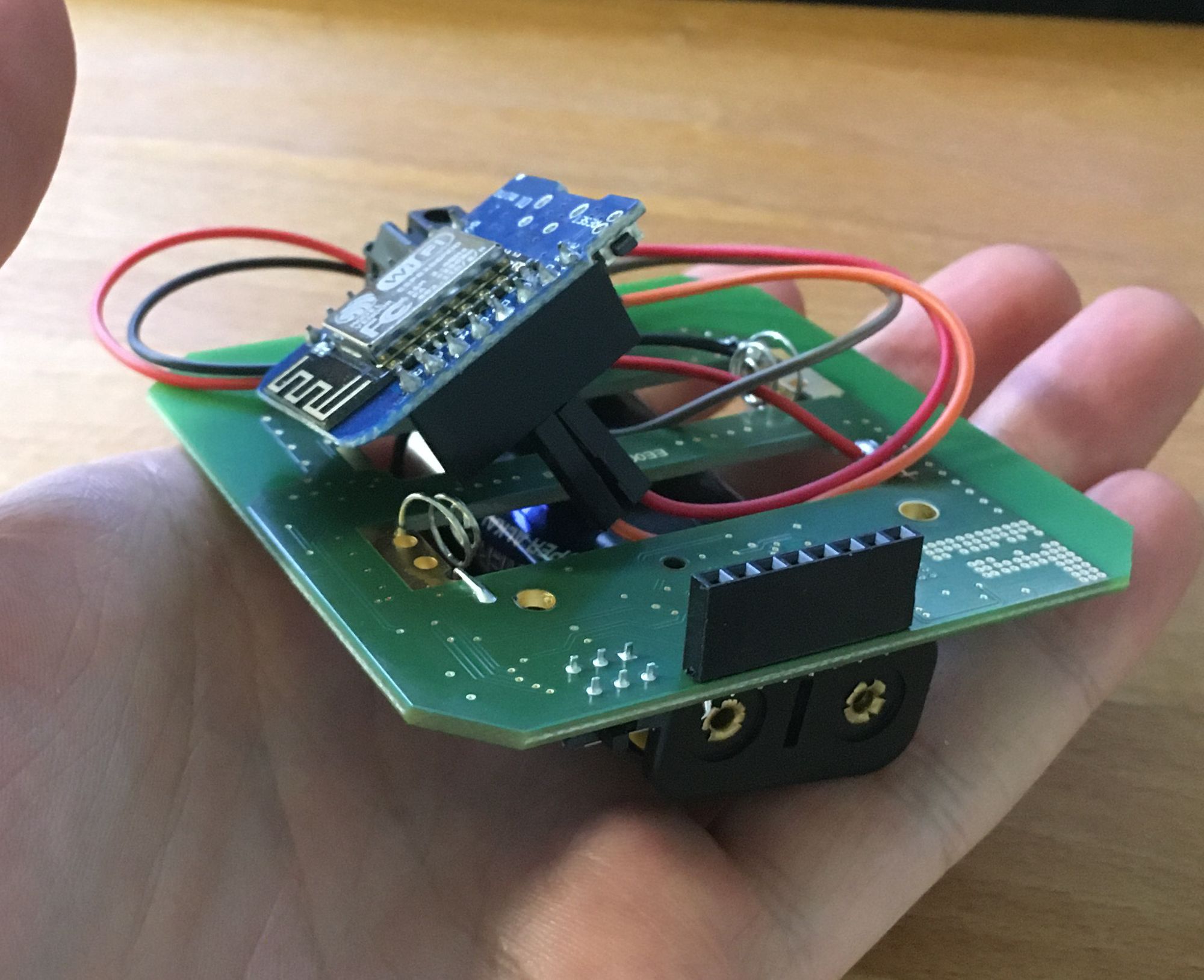
So I went the oldschool way and got direct connection with the switches on the remote control.
Currenty my system can:
- Remote control Hörmann BiSecur devices like gates, motorized garage doors etc.
- Trigger the functionality at an specific time
- Trigger it from everywhere in the world where you have internet access :)
What it not can:
- Request Status of the device e.g. is it open/closed
What you need to build it yourself
- Wemos (Ad - Ref link) or something smiliar to an ESP8266
- Cables and Stuff
- Soldering Iron (nor necessarily)
- a Box to put all the things in
- and 5V Power supply for your ESP8266
- AA or AAA Battery Holder (Ad) for 2 Batteries, alternatively a DC-DC Step Down Module to get the 5V to 3V to supply the Hörmann Module
- You need either Blynk or the Knowledge to build youself an app or integrate it to any other system
What I've done so far
First of all, you don't need much knowledge to do this. It's no "real" hack or
something you just control the switches from your Hörmann remote control and switch them.
Somebody else already did this: https://hackaday.io/project/27570-hrmann-garage-door-remote-hack
I don't like these big relay switches. You can program the pins in the ESP8266 to OPEN_DRAIN. With this the behavior it is like this: When you write 0 to the Pin the pin goes low resistance I measured 50Ohms with my multimeter so not really much. If you write 1 to the pin the resistance is in the mega ohm range. Its called: https://en.wikipedia.org/wiki/Open_collector and it really just behaves like a switch.
So this is nice. We have a functionality with our ESP8266 to switch switches. :) The next thing is what pins to use on an ESP8266. Luckily there is this webiste: https://espeasy.readthedocs.io/en/latest/Reference/GPIO.html#best-pins-to-use-on-esp8266
So if you don't use any I2C devices you have: D1, D2, D5, D6, D7 at your disposal to switch the Hoermann switches. This is really important because you don't want that pins activate on an reset or if you upload a new binary. So next thing was I went on Amazon and bought some remote controls:
- FIT2-1BS Wandtaster/Funk-Innetaster (Ad - Amazon Ref link)
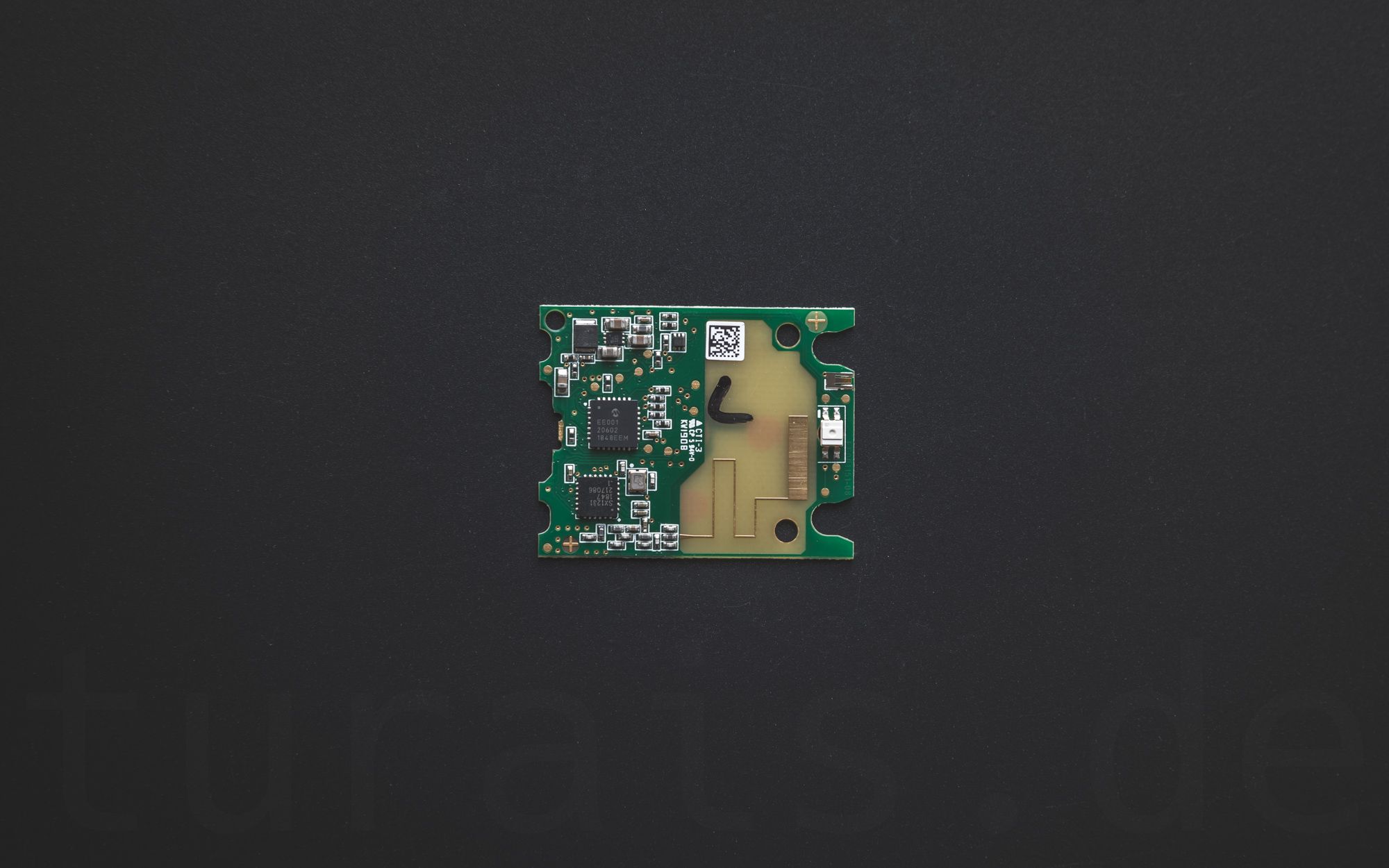
The nice thing on the above one is if you only need the trigger functionality you can go with this one without soldering :) and you can use the switches manually and it looks cool. Additionally you have an hardware switch on the side to deactivate the switches. This is not bad at all for example if you want to disable the online switching ability. Internally it looks like this:
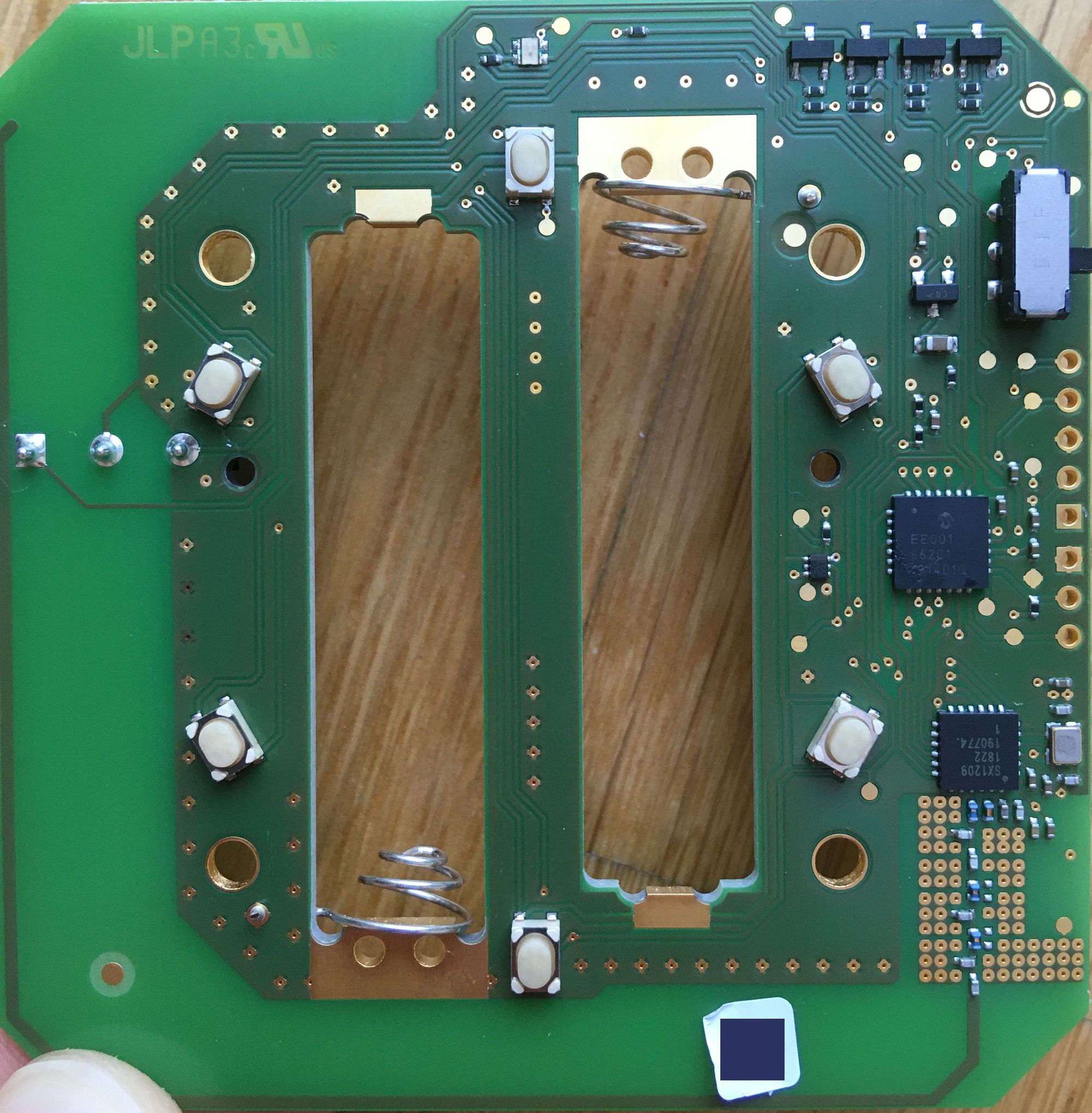
The microcontroller is an PIC18F2XK20 in an 28-PIN Package.
The transceiver is an Semtech SX1209.
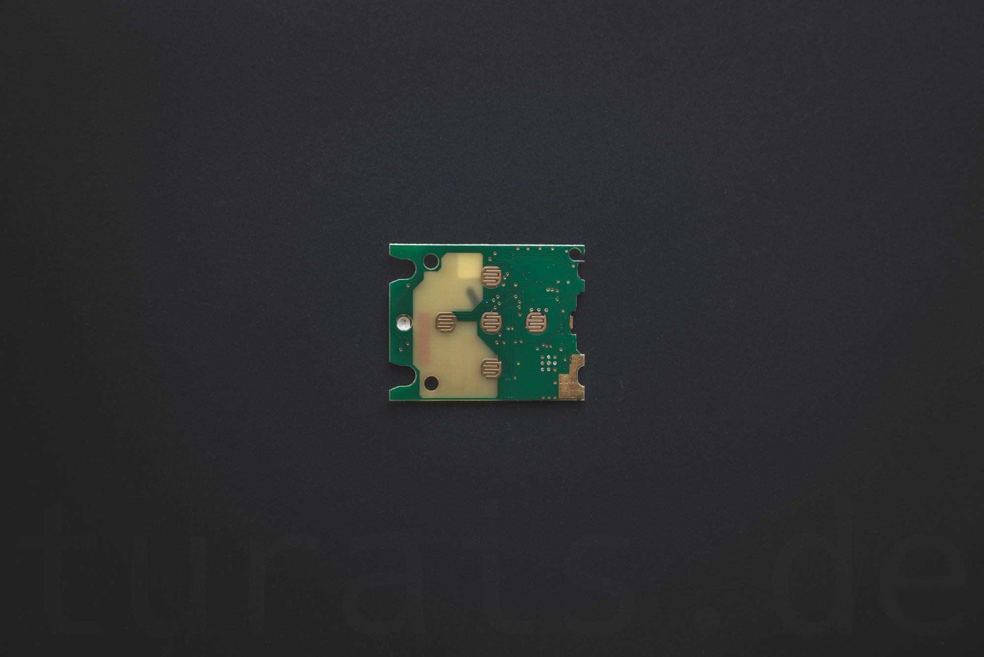
On the other side of the board there is a connection panel where you can connect 2 external switches. So just the right thing for your microcontroller. (If you don't want to solder on to those little switches.) Also really nice on the right there are some breakout pins. I already have soldered an header on that so I can look at some signals. Actually there are 6 switches on this board and not only 2 ;) so if you need an "cheap" (~50EUR) Bi-Secur 6-Channel switch here you go.
Request Status Pin
The next thing I was hoping that the request pin for requesting status of devices like open/closed is on this board and also maybe already in switch form. sadly this isn't the case. I opened another board with the status request functionality.
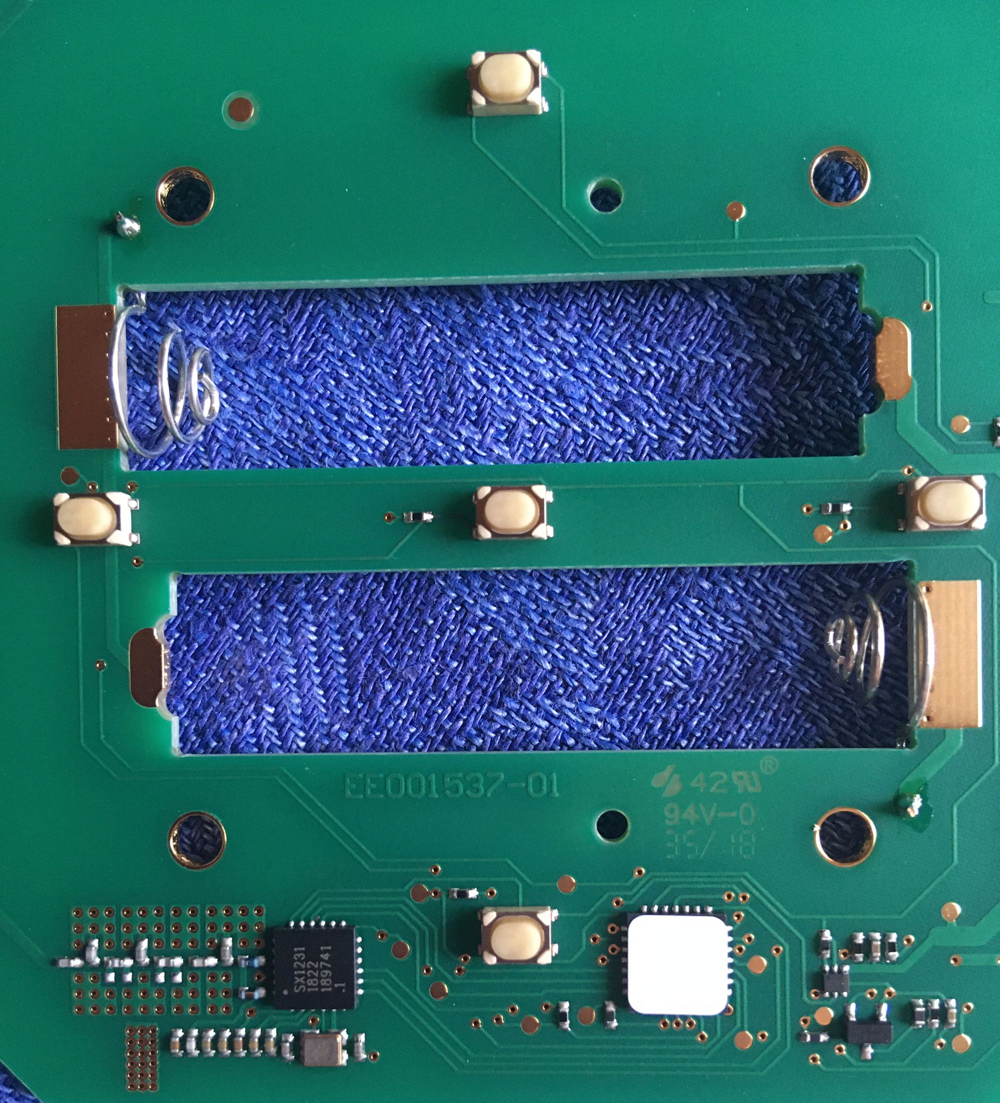
The middle button is the interesting one it's there for requesting the status. And it goes right into pin 28 (RA1/AN1/C12IN1) which is not connected on the other device. And maybe it's not implemented in this firmware version. The next things I bought is one of the: Hörmann 436946 Handsender HS5 (Ad - Amazon Ref link) On this one I'm planning to connect to the pins from the RGB Led and read the status from it.
Like this: Pressing Status Button --> Pressing Button of Device --> Read LED Status
This is work in progress.
Code
I will just post it here so you have an overview and then I'll go through the code later.
#define BLYNK_PRINT Serial
#include <Arduino.h>
#include <ESP8266WiFi.h>
#include <BlynkSimpleEsp8266.h>
#include <Wire.h>

#define DEBUG true
#define TIME_BUTTON_PROGRAM_MS 20000

static char auth[] = "YOUR_AUTH_KEY";
static char ssid[] = "YOUR_WIFI_SSID";
static char pass[] = "YOUR_PASSWORD";

bool enabled = false; //< gets set by application
bool timer_enabled = false; ///< set by app
bool half_open_enabled = false; ///< set by app

static uint8_t pin_a = D5;
static uint8_t pin_b = D6;

BlynkTimer timer_pin_a;
BlynkTimer timer_pin_b;
BlynkTimer timer_half_open;

int time_button_press = 1; ///< in seconds
int time_half_open = 15; ///< in seconds

///---------- HELPERS ----------

static void debug_print(const char *format, ...) { ///< if compiled with at least -O1 this function call gets optimized away if DEBUG = false;
  if(DEBUG) {
    int now = (int)(millis()/1000);
    Serial.printf("[%i] ", now);
    va_list arg;
    va_start(arg, format);
    char temp[64];
    char* buffer = temp;
    size_t len = vsnprintf(temp, sizeof(temp), format, arg);
    va_end(arg);
    if (len > sizeof(temp) - 1) {
        buffer = new char[len + 1];
        if (!buffer) {
            return;
        }
        va_start(arg, format);
        vsnprintf(buffer, len + 1, format, arg);
        va_end(arg);
    }
    len = Serial.write((const uint8_t*) buffer, len);
    if (buffer != temp) {
        delete[] buffer;
    }
  }
}

static inline int seconds_to_ms(int s) {
  return s * 1000;
}

static void pin_write(int pin, int val) {
  debug_print("pin_write(%i, %u) \n", pin, val);
  digitalWrite(pin, val);
}

static void deactivate(void *pin) {
  uint8_t *p = (uint8_t*)(pin);
  pin_write(*p, 1);
}

static void push_button(uint8_t *pin, uint16 ms_pressed, const int val, timer_callback_p f, BlynkTimer *timer) {
  if(enabled && (val == 0)) {
    pin_write(*pin, val);
    timer->setTimeout(ms_pressed, f, pin);
  }
}

///---------- PIN_A ----------

static void trigger_a(int val) {
  push_button(&pin_a, seconds_to_ms(time_button_press), val,
  deactivate, &timer_pin_a);
}

static void execute_a() {
  trigger_a(0);
}

///---------- PIN_B ----------

static void trigger_b(int val) {
  push_button(&pin_b, seconds_to_ms(time_button_press), val,
  deactivate, &timer_pin_b);
}

static void execute_b() {
  trigger_b(0);
}

///---------- OTHER ----------

static void execute_half_open(void (*f)()) { //function f will be called after halfopen_duration (to stop the gate moving)
  debug_print("half opening. stopping gate after: %is \n", time_half_open);
  timer_half_open.setTimeout(seconds_to_ms(time_half_open), f);
}

///---------- BLYNK WRITES ----------

BLYNK_WRITE(V0) { ///< pushing button 1
  int val = param.asInt();
  trigger_a(val);
}

BLYNK_WRITE(V1) { ///< pushing button 2
  int val = param.asInt();
  trigger_b(val);
}

BLYNK_WRITE(V2) { ///< Enable/Disable
  int val = param.asInt();
  enabled = val;
  debug_print("enabled: %i \n", val);
}

BLYNK_WRITE(V3) { ///< programming button 1
  push_button(&pin_a, TIME_BUTTON_PROGRAM_MS, param.asInt(), deactivate, &timer_pin_a);
}

BLYNK_WRITE(V4) { //programming button 2
  push_button(&pin_b, TIME_BUTTON_PROGRAM_MS, param.asInt(), deactivate, &timer_pin_b);
}

BLYNK_WRITE(V5) { ///< setting button press time
  time_button_press = param.asInt();
  debug_print("press_duration: %i \n", time_button_press);
}

BLYNK_WRITE(V6) { ///< setting half open time. [TRIGGER] ... (waiting time_half_open) ... [TRIGGER]
  time_half_open = param.asInt();
  debug_print("half_open_duration: %i \n", time_half_open);
}

BLYNK_WRITE(V7) { ///< disable/enable half open mode
  int val = param.asInt();
  half_open_enabled = val;
  debug_print("half open enabled: %i \n", val);
}

BLYNK_WRITE(V8) { ///< trigger_a from timer
  if(timer_enabled) {
    int val = param.asInt();
    if(val == 1) {
      debug_print("from timer triggering PIN_A\n");
      execute_a();
    }
  }
}

BLYNK_WRITE(V9) { ///< disable/enable timers
  int val = param.asInt();
  timer_enabled = val;
  debug_print("timers enabled: %i \n", val);
}

BLYNK_CONNECTED() {
  Blynk.syncVirtual(V9); //enable/disable timers
  Blynk.syncVirtual(V8); //trigger_a from timer
  Blynk.syncVirtual(V7); //
  Blynk.syncVirtual(V6);
  Blynk.syncVirtual(V5);
  Blynk.syncVirtual(V2);
  Blynk.syncVirtual(V1);
  Blynk.syncVirtual(V0);
}

///---------- MAIN STUFF ----------

void setup() {
  pinMode(D5, OUTPUT_OPEN_DRAIN);
  pinMode(D6, OUTPUT_OPEN_DRAIN);
  digitalWrite(D5, 1);
  digitalWrite(D6, 1);

  Serial.begin(9600);
  Blynk.begin(auth, ssid, pass, "yourblynkserver.example.com", 8442);
}

void loop() {
  Blynk.run();
  timer_pin_a.run();
  timer_pin_b.run();
  timer_half_open.run();
}
If you want to use this code right away you have to change a few things before uploading.
Changing things before uploading it to your ESP8266
First of all:
static char auth[] = "YOUR_AUTH_KEY";
static char ssid[] = "YOUR_WIFI_SSID";
static char pass[] = "YOUR_PASSWORD";
Change this to your wifi and change YOUR_AUTH_KEY to your Blynk-Project auth key. You can get it in your Project Settings under "Auth Token".
static uint8_t pin_a = D5;
static uint8_t pin_b = D6;
Change this to your used pins.
Blynk.begin(auth, ssid, pass, "yourblynkserver.example.com", 8442);
and of course this line, either to your own Blynk server or the official one. More on how to setup your Blynk Project: https://docs.blynk.cc/
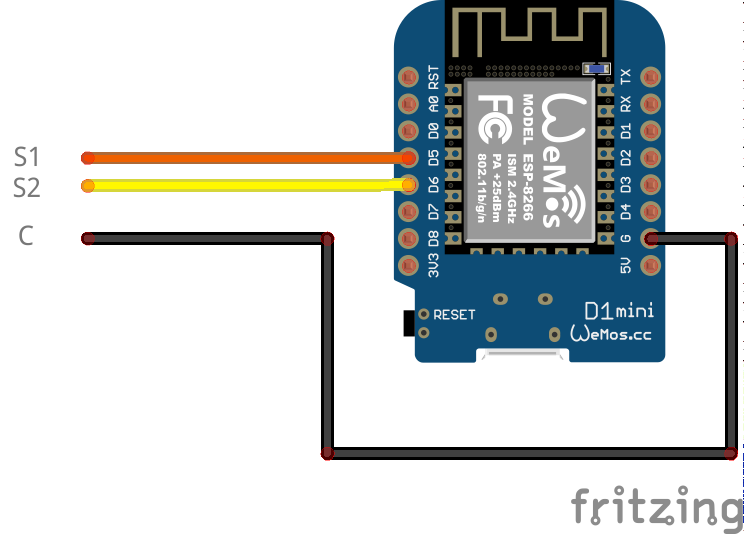
In case you have another remote control: solder the ground from your ESP8266 to the ground connector at the battery connection. One ground-battery connection is connected to the other plus-battery connection so be careful. (two batteries in series)
The code in detail
///---------- MAIN STUFF ----------

void setup() {
  pinMode(D5, OUTPUT_OPEN_DRAIN);
  pinMode(D6, OUTPUT_OPEN_DRAIN);
  digitalWrite(D5, 1);
  digitalWrite(D6, 1);

  Serial.begin(9600);
  Blynk.begin(auth, ssid, pass, "yourblynkserver.example.com", 8442);
}
Here it is important to use the pins as OUTPUT_OPEN_DRAIN.
We go through one "virtual"-button click.
First of all in your Blynk app:
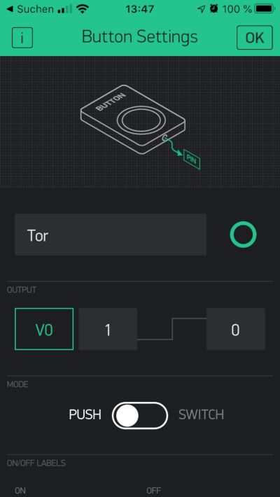
From 1 to 0.
I set the to push mode and then to switch from 1 to 0. Of course you can change this but you have to do minor changes in code. So if you press the button in the Blynk-App. The command gets forwarded to the Blynk server and the ESP8266 asks the server if he got some new messages for him. Then we're here:
BLYNK_WRITE(V0) { ///< pushing button 1
  int val = param.asInt();
  trigger_a(val);
}
This looks funny it's an macro that expands to an function so don't worry. Nevertheless you can get the parameter as an integer with this call.
///---------- PIN_A ----------

static void trigger_a(int val) {
  push_button(&pin_a, seconds_to_ms(time_button_press), val,
  deactivate, &timer_pin_a);
}
this is the trigger function for pin_a. It "pushes" the button. I have this function so I can trigger_a not only from BLYNK_WRITE(V0).
static void push_button(uint8_t *pin, uint16 ms_pressed, const int val, timer_callback_p f, BlynkTimer *timer) {
  if(enabled && (val == 0)) {
    pin_write(*pin, val);
    timer->setTimeout(ms_pressed, f, pin);
  }
}
This is more interesting, it pushes the button connected to pin pin for an amount ms_pressed.
The behavior from an button press is something like this: Button gets pressed for an specific time and then the button gets released. This behavior is already implemented in the Blynk App. When you set the Blynk Button to PUSH-Mode it sends the second value for a short amount of time and then sends the initial value. But for our purpose this is way too short. The Hörmann remote only detects button presses longer than approx. 1 second. The other thing I found is that the longer you press the button the signal from the Hörmann remote gets repeated more often. So If I press a button only once for a short time it can happen my gate won't trigger at all. If I press the button longer than it always triggers. Thats why you can change the trigger time directly from the app, so you can find the duration you need.
Back to the function. I use an BlynkTimer with the option setTimeout
    // Timer will call function 'f' with parameter 'p' after 'd' milliseconds one time
    // returns the timer number (numTimer) on success or
    // -1 on failure (f == NULL) or no free timers
    int setTimeout(unsigned long d, timer_callback_p f, void* p);
So it will call the function f with parameter pin after the time ms_pressed. The function f is in this case:
static void deactivate(void *pin) {
  uint8_t *p = (uint8_t*)(pin);
  pin_write(*p, 1);
}
Pin write:
static void pin_write(int pin, int val) {
  debug_print("pin_write(%i, %u) \n", pin, val);
  digitalWrite(pin, val);
}
I only have this function because I wanted to put an debug_print here.
If you have any questions please write down in the comments below, I try to answer them.
Thanks :)
- Hörmann Handsender - 4 Tasten
- Hörmann Handsender mit Abfragetaste
- Hörmann Wandtaster used in this Article
- Hörmann Wallswitch with Status Request
Disclaimer: Article contains ref links to Amazon/Aliexpress if you
click and buy you support my blog and investments in future electronic
stuff :) I marked the links with (Ad)
If you press this Button it will Load Disqus-Comments. More on Disqus Privacy: Link