

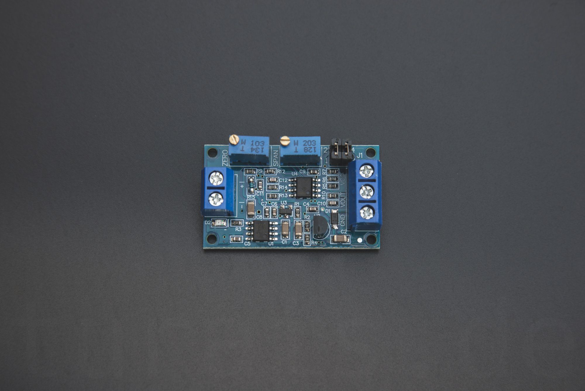
You can find the Current to Voltage Module HW-685 on Ebay and Aliexpress. With this module you can transform the current readings into voltage and later on read this voltage with your ADC on your Microcontroller. For example with an ESP8266 or an Arduino.
If youre looking for a basic documentation, maybe my documentation is something for you: https://docs.turais.de/docs/modules/hw685/
Why does the Sensor outputs current in the first place?
It's a de facto standard for PID Controllers, SCADA Systems and PLCs (Programmable Logic Controllers). In harsh environments it is in some cases better to transmit the information via current instead of voltage.
There are different solutions for transmitting data, like RS-485. But the most easiest one is transmitting the information via current. Most industrial sensors you find on Ebay or Aliexpress use this standard. This has many advantages:
- Only 2-Wires are needed, the sensor gets its power via the power cables and also transmits its reading over power usage.
- High noise immunity.
- Self monitoring: 4-20mA means sensor is working fine, below or more means there is an error with your sensor.
You can read more about the current loop on wikipedia.
How to get some readings
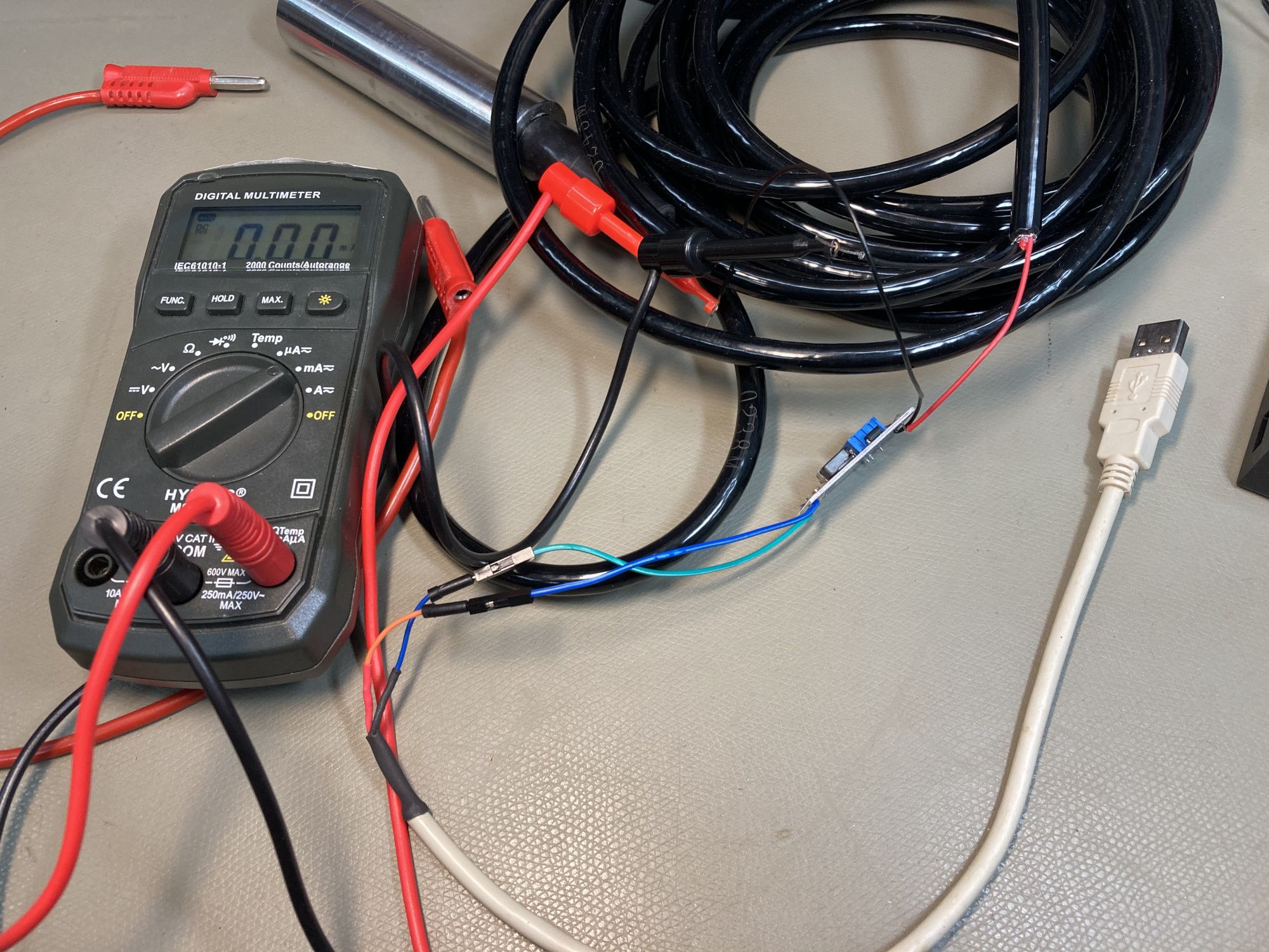
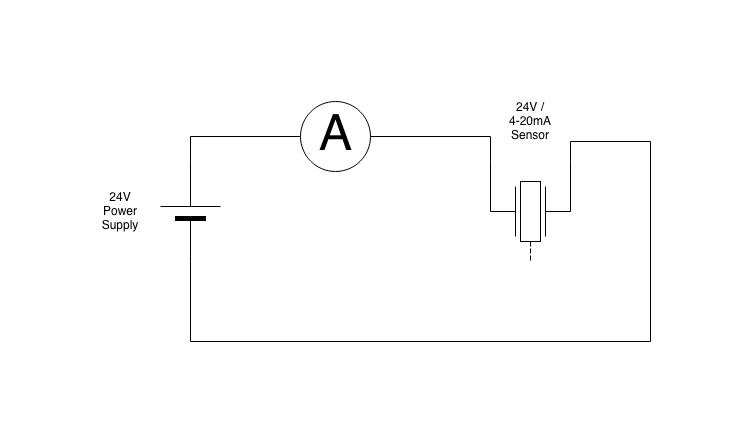
The easiest way for a simple test is just to use your multi-meter in current mode. Power your sensor with the given supply voltage and the sensor should return a reading. Don't forget that if you want to read current, you have to put your multi meter in current mode and in series to the sensor.
To automate that reading you could put an resistor in series (~200-250Ohms) and measure the voltage drop before the resistor.
One major disadvantage I found, is that you get 0.88V @4mA and 4,4V @20mA, so you're not using the full potential of your ADC.
But in most cases this will be enough. And of course the cheapest solution.
A good example can be found here: https://arduino.stackexchange.com/questions/45485/reading-4-to-20ma-pressure-sensor-using-uno
How to get readings with the Module?
Connect your Sensor like following:
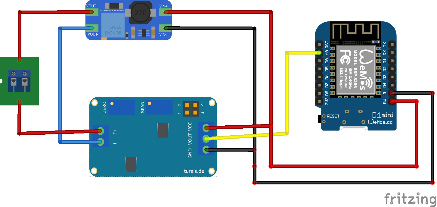
When your +5V is not constant, like from USB: either use an dedicated +5V Voltage Regulator. Using the 3.3V from your WEMOS won't work, because the module works only with +5V upwards.
- For the 24V Power Supply I'm using a Step-Up from Aliexpress.
They're really cheap and it doesn't hurt to have some in your inventory. Supply the Step-Up with your +5V (can vary) and then turn the knob until your multi-meter reads 24V. Turning the potentiometer can take some time. At the beginning (from left to right) you'll read a voltage from VOUT to GND, below your supply voltage. Now turn your potentiometer to the right until you get your 24V. To get the 24V on point you need to turn the potentiometer really slow.
Selecting your Output Voltage
You can select your output voltage by connecting the jumpers labeled on your board as J1.
- 0-3.3V: Remove all jumpers (at least 5.0V supply voltage)
- 0-5V: 1-2 connected, 3-4 connected (at least 7V supply voltage)
- 0-10V: 1-2 connected, 3-4 disconnected (at least 12V supply voltage)
- Turn all the potentiometers to the left. You can hear a little click if the leftmost position is reached. Don't worry you can't really overturn them.
- Connect your Sensor like the schematic above.
- Measure with a multi-meter the vout Voltage from vout to ground.
- Now turn the Zero multi-meter to a voltage that you'll later define as zero. You can turn so that you're reading is
0.00, but then you won't be able to detect a sensor failure. - I then connected a variable resistor with a multi-meter in ampere mode in series and turned the resistor knob, so that it read exactly 20mA. Turn the SPAN resistor knob to the right until it reads exactly 3.00V.
This will give you me an effective range between 0.2V-3V where 0.2V represents 4mA and 3V: 20mA.
Disadvantages
The major disadvantage in this setup for measuring currents from 4-20mA is, that you need an constant voltage +5V supply. USB won't work because USB voltage can vary by +0.25V and -0.55V if your supply is in the specification.
I discussed earlier that you can use an resistor and measure the voltage drop on your resistor. The disadvantage with the resistor model would be that you don't utilize the full range of your ADC. But its way cheaper and you don't need a constant voltage supply for the module only a constant voltage for your sensor.
If you press this Button it will Load Disqus-Comments. More on Disqus Privacy: Link