
There comes a time you just want to test your code. For example if you write some control for a watering system you want to drive some pumps and or toggle valves.
For that you drive an ULN2803 or an MOSFET. But it is too cumbersome to test and debug everything on the real hardware.
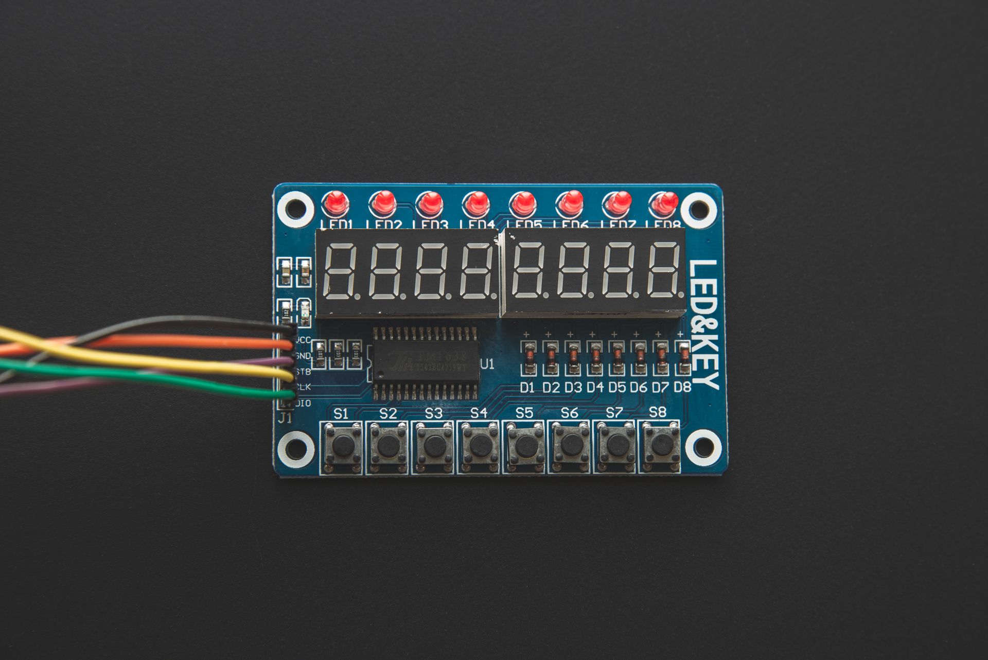
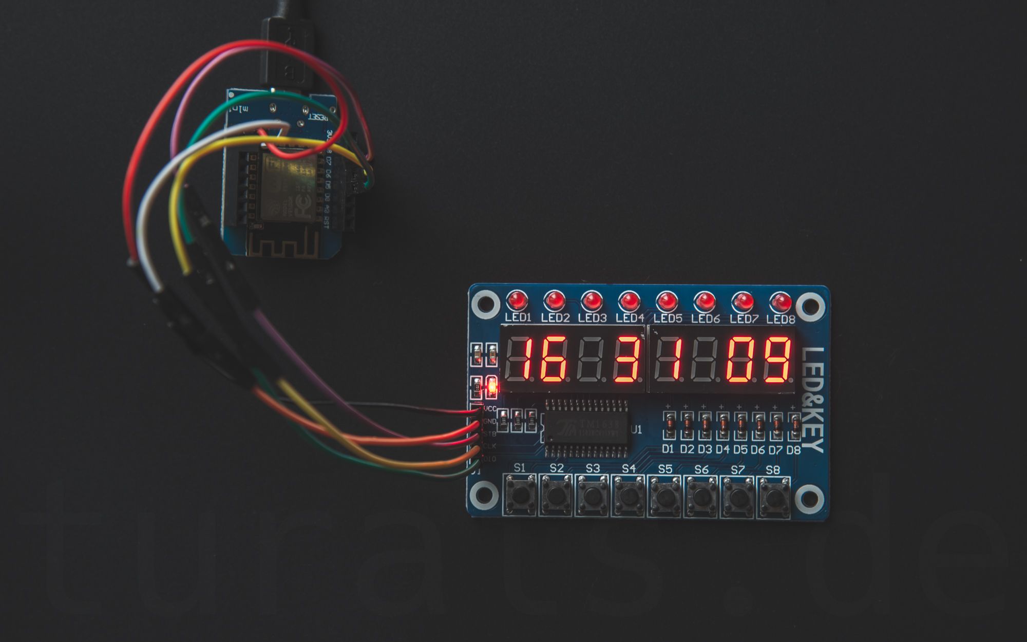
For that purpose there is a board you need - the LED&KEY TM 1638 Board. It's easy to use, and you can really do a lot of stuff with it. But bear in mind, toggling a led is not that easy like an digitalWrite.
I wrote an small Documentation about this Module in my newly created Docs-Section. You can read about it here:
How to connect?
TM1638(byte dataPin, byte clockPin, byte strobePin, boolean activateDisplay = true, byte intensity = 7);
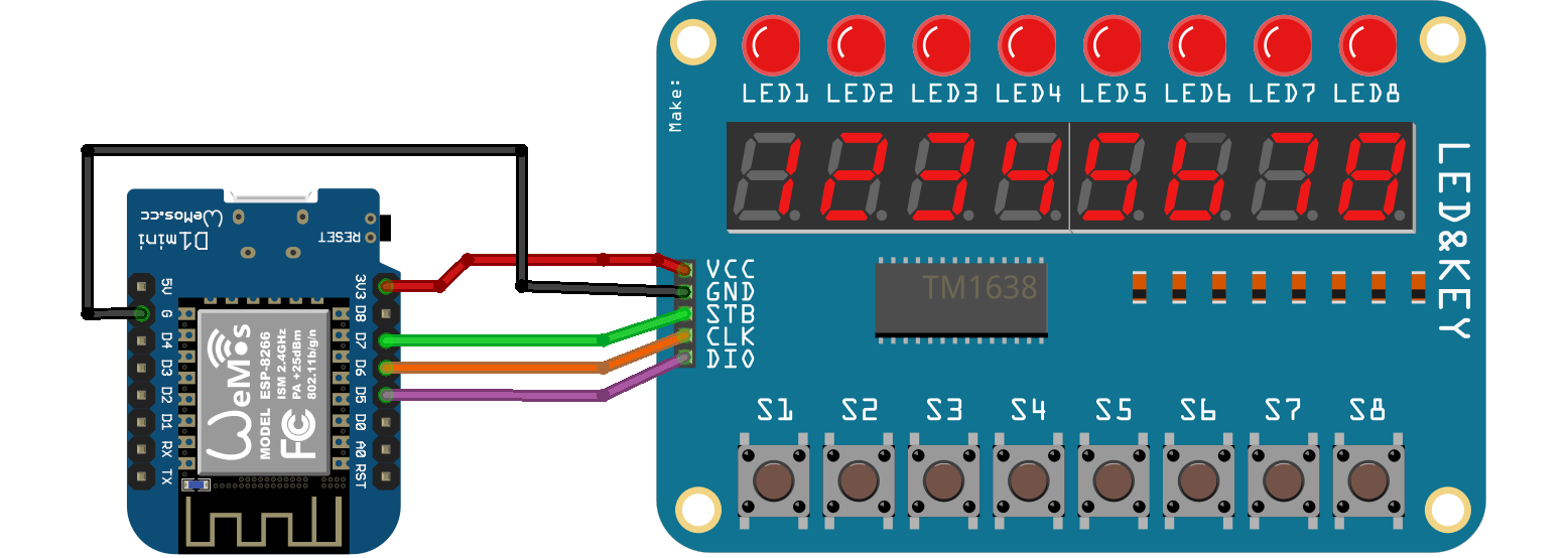
This is the definition of the TM1638 constructor. I used an WEMOS D1 Mini with an ESP8266. You initiate your TM1638 module like so:
TM1638 module(D5, D6, D7);
So I'm using D5 as the dataPin, D6 the clockPin and D7 as the strobePin.
What library to use
You can use the TM1638 Library from Ricardo Batista. https://github.com/rjbatista/tm1638-library
You have to change the min-function used in this library if you want to use this library with an ESP8266 or an ESP32. Or use my fork.
Here is my diff:
44c44 < sendCommand(0x80 | (activateDisplay ? 8 : 0) | _min(7, intensity)); --- > sendCommand(0x80 | (activateDisplay ? 8 : 0) | min(7, intensity)); 56c56 < sendCommand(0x80 | (active ? 8 : 0) | _min(7, intensity)); --- > sendCommand(0x80 | (active ? 8 : 0) | min(7, intensity)); 179a180 >
I changed min to _min.
As the owner is not accepting pending pull-requests you can use my fork instead: https://github.com/turais/tm1638-library
How do I power an LED?
Basically you write an byte to an address. Like so:
ledkey_module.setLEDs(led_state);
Every bit in this byte represents one of those LEDs. For example:
| Bit# |  8  |  7  |  6  |  5  |  4  |  3  |  2  |  1  | +------+-----+-----+-----+-----+-----+-----+-----+-----+
|      | 2^8 | 2^7 | 2^6 | 2^5 | 2^4 | 2^3 | 2^2 | 2^1 |
| VAL: | 0   | 0   | 0   | 0   | 0   | 1   | 1   | 0   | +------+-----+-----+-----+-----+-----+-----+-----+-----+
this would be the value: 0x06. To calculate easily you could create an enum:
enum {
  LED1 = 0u,
  LED2 = 1u,
  LED3 = 2u,
  LED4 = 4u,
  LED5 = 8u,
  LED6 = 16u,
  LED7 = 32u,
  LED8 = 64u
};
If you defined this enum you can easily use that in your setLEDs.
ledkey_module.setLEDs(LED1 | LED5 | LED7);
For setting an specific LED, without destroying the state from already lighted LEDs, I'm using this handy macro I wrote:
#define SET_BIT(A, i, val) \
        do{ A &= ~(1u << i); A |= (val << i); } while(false)
this macro sets bit number i to val in the byte: A. I use an global variable: static word led_state = 0x00; where I 'save' the current state for the LEDs.
Then I wrote myself a nice little function I use for writing to an pin.
static void pin_write(int pin, int val) {
  //#ifdef LOG_TO_APP
  //Blynk.virtualWrite(pin, val);
  //#endif
  pin = pin_mapping[pin];

  word _val = (val == 0) ? 1 : 0;

  //debug_print("pin_write(%i, %u) \n", pin, _val);
  SET_BIT(led_state, pin, _val);
  ledkey_module.setLEDs(led_state);

}
Then you can wrap this in an if-else macro and define an DEBUG variable, so that only this function gets called if you're debugging. If you are using the LED&KEY Module only for debugging, and want to flash the real hardware: you just delete the debug define and you're good to go.
My "production" pin_write-would look like this:
#ifndef NDEBUG

#define SET_BIT(A, i, val) \
        do{ A &= ~(1u << i); A |= (val << i); } while(false)

enum {
  LED1 = 0u,
  LED2 = 1u,
  LED3 = 2u,
  LED4 = 4u,
  LED5 = 8u,
  LED6 = 16u,
  LED7 = 32u,
  LED8 = 64u
};

static word led_state = 0x00;

static void pin_write(int pin, int val) {
  #ifdef LOG_TO_APP
  Blynk.virtualWrite(pin, val);
  #endif
  pin = pin_mapping[pin];

  word _val = (val == 0) ? 1 : 0;

  debug_print("pin_write(%i, %u) \n", pin, _val);
  SET_BIT(led_state, pin, _val);
  ledkey_module.setLEDs(led_state);

}
#else
static void pin_write(int pin, int val) {
  #ifdef LOG_TO_APP
    Blynk.virtualWrite(pin, val);
  #endif
  debug_print("pin_write(%i, %u) \n", pin, val);
  digitalWrite(pin, val);
}
#endif
I use an define LOG_TO_APP if I want to write some data to my Blynk-App, otherwise, the code above is self explanatory. If you have some questions, please write in the comments below. (Really I mean it don't hesitate)
And of course I have the TM1638-Module defined above. Like so:
#ifndef NDEBUG
TM1638 ledkey_module(D5, D6, D7);
#endif
I used D5, D6 and D7 on an WEMOS D1 Mini to connect the board.
Reading Key Presses
Look below for the working example below, for how to poll the key presses. I poll them every 50ms.
Writing something to the Display
It's easy:
String str = "0123ABCD";
module.setDisplayToString(str);
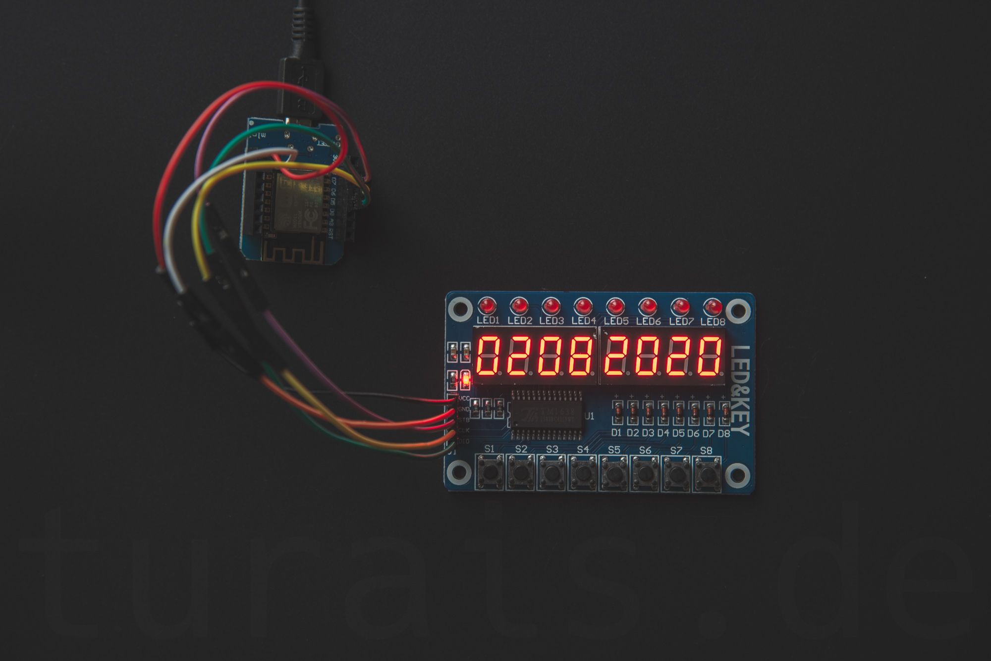
ESP8266 NTP Clock and Date with LED&KEY Display
Check out my repository. It's an simple LED&KEY example which displays the date or the time. You can change the display by pressing Button 2.
To read a button press with the LED&KEY Module, you can use the library function: getButtons(). This call gives you a byte, and in this byte every bit is representing the button from left to right.
So for example if your byte looks like this: 0x01 , Button 1 is pressed. 0x02 for Button 2. Combinations out of more than one button press give you for example: 0x22. If you look at this in binary everything is clear: 0010 0010b reading from right to left. So the LSB gives you the state of button 1.
In the case of 0x22 Button 2 and Button 6 is pressed. To read those conveniently I used an ENUM:
typedef enum {
  BTN1 = 1,
  BTN2 = 2u,
  BTN3 = 4u,
  BTN4 = 8u,
  BTN5 = 16u,
  BTN6 = 32u,
  BTN7 = 64u,
  BTN8 = 128u
} BTN;
To get only the state from one button you could do something like this:
void get_pressed(const byte &state, const BTN check, bool &pressed) {
    byte btn_state = (state & check);
    pressed = btn_state / check;
}
If you have questions, please post a comment below :)
If you press this Button it will Load Disqus-Comments. More on Disqus Privacy: Link